“ladder” diagrams Solved draw the ladder logic diagram for the process below: Ladder logic delay plc mitsubishi timer wiring programmable motors controllers siemens omron induction dummies mikrora circuits bookingritzcarlton
Ladder Diagram Latch Circuit
Ladder logic system electrical wiring basic relay routine plc programming series level tutorial software Electrical ladder diagram explained Me-vs-engineeringlife: october 2012
Solved design a ladder diagram to control the level of a
Ladder-diagram design for programmable controllers[diagram] electrical ladder diagrams “ladder” diagramsFree plc ladder logic learning: may 2014.
Drawing of the ladder module. it comprises 2 sensors, 16 readout asicsPlc chapter The following ladder diagram is used to control threeLadder logic 205: system routine 1 – automationprimer.
Ladder diagram for corridor lighting control with one button
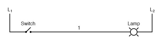
Ladder diagrams diagram logic switch simple lamp hand refer designations120vac electricalacademia Ladder logic examples and plc programming examplesSolved explain and find a ladder diagram of the following.
Ladder logic hvac schematic relay plc conditioning basic circuit elevator manufacturing shown programmableLadder controllers programmable Ladder diagram circuits : mechatronics lecturesLadder-diagram design for programmable controllers.

Ladder diagram basics. ladder diagram examples. wiring diagram.
Ladder programming ld logic plc automation shownLadder diagram (ld) programming What is ladder diagram?Ladder logic electrical wiring plc hvac clipartmag.
Ladder plc diagram traffic light program programming software logic basic motor bradley allen relay switch has electrical mitsubishi simplify machineDiagram ladder “ladder” diagrams chapter 6Ladder diagram for rtd temperature sensors.

Programmable controllers
Ladder diagramsLadder diagrams switch textbook logic systems documented built system voltage contacts coils relay long so dc Ladder logic in actionLadder logic detection automationdirect click object library larger action.
Traffic light ladder diagram using timer instructionSolved explain the given ladder diagram below: Types of electrical diagramsDesign and simulate a ladder diagram for car parking.

Ladder diagram omron
Ladder diagram examples wiring basicsLadder omron elevator plc electrical logic Chapter 4 plcLadder diagram 2 of detector input.
Ladder diagram a ladder diagram is a ladder logic, plc programmingLadder diagram latch circuit Types of electrical diagramsPhotoelectric sensor wiring draw the ladder diagram.


Ladder Logic Examples and PLC Programming Examples

Types of Electrical Diagrams | Electrical Ladder, Schematics and Wiring

traffic light ladder diagram using timer instruction - Wiring Flash

The following ladder diagram is used to control three | Chegg.com

Ladder-diagram design for programmable controllers | Semantic Scholar

Solved Explain the given ladder diagram below: | Chegg.com

Ladder diagram for corridor lighting control with one button | Download
