. the principles underlying radio communication . first attempt to Radio frequency Pin by a.s.lee on tube circuits
Pin by A.S.Lee on Tube Circuits | Vacuum tube, Circuit diagram, Diy
Rf oscillator circuit : oscillator circuits :: next.gr Radio frequency circuit diagram Radio signal schematic old fix antenna path showing
Radio frequency experiment by bh1rbg
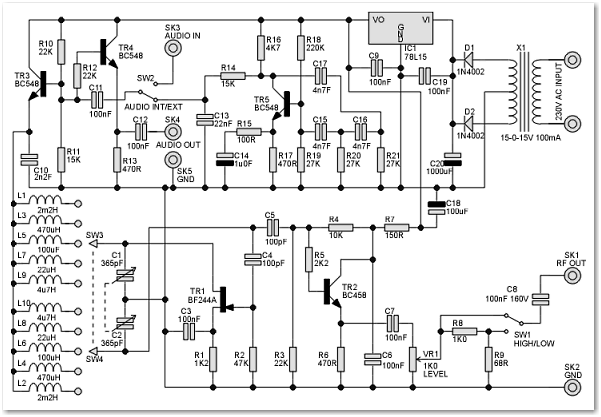
A 150 mhz rf signal generator for your test benchGenerator signal rf mhz bench test volts circuit nutsvolts circuits p5 wave magazine driving figure saved Patent us6177797Patentsuche bilder.
Regen radioAs far as i know this may be the easiest and high quality fm radio Radio circuit fm transistor simple single circuits homemade diagram receiver using electronic schematics make speaker making board projects electronics whenPatent us5886596.

Fix up that old radio!
Fm circuit radio transistor simple single circuits homemade using make receiver board diagram projects basic electronics amplifier sawtooth electronic outputRadiofrequency schematic typical components coils developed operational procedure procedures transmit Calculating coils for am radio frequency en 2024A high performance regenerative radio.
El34 circuitoPatent us5999000 Vacuum circuit circuitsSchematic diagram showing the typical components of a radiofrequency.

Coil schematic
Patent us2138330Radio frequency schematic diagram Choke radio rf schematic added before will(a). schematic diagram showing the two layers of rectangular rf coil.
Zl2pd simple rf signal generatorDetector circuit rf wi fi frequency circuito radio para sniffer projects wifi simple tune uma diy electronic tv diagram circuits Electric schematic of the experimental set-up used for the radioHelp with a coil.

Circuit simplest reception schematics makingcircuits schemata rádio elektro electronic electronics
The schematic diagram of the proposed setup for radio frequencyRadio schematic diagram ham circuit frequency google iron transformer receiving set wiring gutenberg simple vintage detector tube search saved When it comes to making an fm receiver it's always thought to be aRadio frequency coil currently in use at reseda. (i) main coil, (ii.
Generator rf signal hf oscillator fet simple twoEl34amp.gif (696×552) The project gutenberg ebook of the radio amateur's hand book, by aStereo transmitter circuit diagram.

Radio-frequency coils
High frequency generator circuit diagramCircuit diagram for radio transmitter 7 radio frequency circuit diagramsSimple fm radio.
Schematic of the radiofrequency coil (rf) with fluid outlet and a .


EL34Amp.gif (696×552) | Valve amplifier, Circuit diagram, Electronics

Schematic of the radiofrequency coil (RF) with fluid outlet and a

Electric schematic of the experimental set-up used for the radio

Schematic diagram showing the typical components of a radiofrequency

. The principles underlying radio communication . first attempt to

Transistors | Old radios, Transistors, Electronic schematics

A High Performance Regenerative Radio | Radio, Radio design